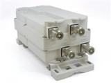
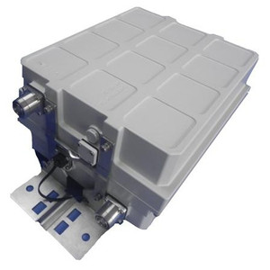
CommScope 850/1990 MHz Dual Band Tower Mounted Amplifier
$1,641.89
- Brand
- CommScope
- SKU:
- ETD819HS12UB
- Weight:
- 25.55 LBS
- Shipping:
- Calculated at Checkout
OneBase™ Diplexed Dual Band Tower Mounted Amplifier
850/1900 MHz TMA for Diplexed Feeder
Designed for the highest reliability even in the most demanding installation environments.
The tower mounted amplifiers from Andrew Solutions help optimize network performance and represent the ideal solution for coverage and capacity enhancement.
By improving uplink performance, Andrew Solutions tower mounted amplifiers (TMAs) ensure optimum coverage of fringe areas, weak spots, and indoor locations. Easily installed in any wireless system, TMAs provide multiple benefits:
Improved sensitivity—reducing dropped calls and failed connection attempts. Enhanced signal quality—improving voice clarity and data speed. Lower handset output—extending talk time, reducing interference in GSM/EDGE, UMTS, and CDMA systems.
The dual band, dual duplex TMA is part of the OneBase™ product family, which combines the Andrew Solutions products and technology into complete solutions for use in integrated base station systems. The self-contained body is engineered to ensure the highest reliability in severe environments while featuring a compact size and attractive appearance.
- Full band operation in both 850 and 1900 MHz bands
- Diplexed BTS and Antenna ports for shared feeder
- Dual protocol AISG 1.1/2.0 support
- SMR rejection against interference from public safety and trunking transmitters
- Lightning protection—built-in multi-stage surge suppressor
- In-line connectors
- Failsafe low noise amplifier (LNA) bypass
- Defaults to legacy-compatible dc mode for non-AISG applications
- Field upgradeable firmware
| Electrical Specifications Rx (Uplink) | |
| Bandwidth | 60.00 MHz |
| License Band | PCS |
| Frequency Band | 1850 – 1910 MHz |
| Gain | 12 dB |
| Gain Tolerance | +1.3/-1.0 |
| Noise Figure, Mid Band, typical | 1.60 dB @ 12 dB |
| Noise Figure, Full Band, typical | 1.80 dB @ 12 dB |
| Input P1dB, typical | -1 dBm |
| Output IP3, minimum | 21 dBm @ 12 dB |
| Return Loss, minimum | 18 dB |
| Insertion Loss, Bypass Mode, typical | 2.60 dB |
| Return Loss, Bypass Mode, typical | 18 dB |
| Tx Band Rejection | 80 dB |
| Group Delay Variation, maximum | 100 ns @ 5.00 MHz |
| Total Group Delay, maximum | 180 ns |
| Electrical Specifications Tx (Downlink) | |
| Bandwidth | 60.00 MHz |
| Insertion Loss, maximum | 0.70 dB |
| License Band | PCS |
| Frequency Band | 1930 – 1990 MHz |
| Return Loss, minimum | 18 dB |
| 3rd Order IMD | -112 dBm |
| 3rd Order IMD Test Method | Two +43 dBm carriers |
| Input Power, RMS, maximum | 300 W |
| Input Power, PEP, maximum | 3000 W |
| Group Delay Variation, maximum | 20 ns @ 5.00 MHz |
| Total Group Delay, maximum | 60 ns |
| Electrical Specifications 2 Rx (Uplink) | |
| License Band | Cellular |
| Frequency Band | 824 – 849 MHz |
| Bandwidth | 25.00 MHz |
| Gain | 12 dB |
| Gain Tolerance | +1.3/-1.0 |
| Noise Figure, Mid Band, typical | 1.50 dB @ 12 dB |
| Noise Figure, Full Band, typical | 1.90 dB @ 12 dB |
| Input P1dB, typical | 2 dBm |
| Output IP3, mimimum | 25 dBm |
| Return Loss, minimum | 18 dB |
| Insertion Loss, Bypass Mode, typical | 2.40 dB |
| Return Loss, Bypass Mode, typical | 18 dB |
| Tx Band Rejection | 80 dB |
| Group Delay Variation, maximum | 270 ns @ 5.00 MHz |
| Total Group Delay, maximum | 370 ns |
| Electrical Specifications 2 Tx (Downlink) | |
| Bandwidth | 25.00 MHz |
| Insertion Loss, maximum | 0.60 dB |
| License Band | Cellular |
| Frequency Band | 869 – 894 MHz |
| Return Loss, minimum | 18 dB |
| 3rd Order IMD | -112 dBm |
| 3rd Order IMD Test Method | Two +43 dBm carriers |
| Input Power, RMS, maximum | 500 W |
| Input Power, PEP, maximum | 5000 W |
| Group Delay Variation, maximum | 25 ns @ 5.00 MHz |
| Total Group Delay, maximum | 65 ns |
| Electrical Specifications | |
| Default Protocol | AISG 2.0 |
| Protocol | AISG 1.1 | AISG 2.0 |
| Voltage | 7–30 Vdc |
| Operating Current at Voltage | 240 mA @ 10–18 V |
| Operating Current Tolerance | ±30 mA |
| Alarm Functionality | AISG | Failure current |
| Failure Current Consumption | 30–170 mA @ 10-18 V |
| RET System Compatible | 1 Output, 24 Vdc and RS-485 |
| Lightning Surge Capability Test Method | IEEE C62.42-1991 |
| Lightning Surge Capability Waveform | 8/20 waveform |
| Lightning Surge Current | 5 kA |

 US Dollar


